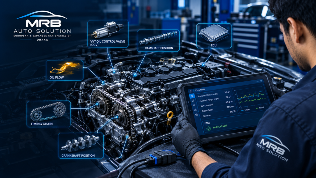
Detailed Toyota VVT Diagnostic Procedure
For the overall diagnostic workflow, start with our automotive diagnostics guide. If the vehicle also has a cam/crank correlation fault, see our Toyota P0016 diagnostic guide and, when service is needed, our car diagnostic scan service in Dhaka.
Toyota Variable Valve Timing (VVT) systems are designed to alter valve timing according to engine speed, load, temperature, and operating conditions. When the system develops a fault, the engine may experience rough idling, poor acceleration, reduced fuel economy, hard starting, or an illuminated Check Engine light.
A VVT-related diagnostic trouble code (DTC) does not automatically mean the VVT actuator, camshaft timing, or timing chain needs replacement. Correct diagnosis requires checking the electrical circuit, engine oil condition and pressure, VVT control valve operation, camshaft position feedback, and mechanical valve timing.
The following procedure provides a systematic diagnostic approach.
1. Confirm the Customer Complaint
Before testing components, establish exactly what the vehicle is doing.
Record:
- Engine model and displacement
- Model year
- Mileage
- Symptoms
- When the problem occurs
- Engine temperature when the fault appears
- Whether the engine starts normally
- Whether the engine stalls
- Whether power is reduced
- Fuel consumption changes
- Recent engine repairs
- Recent oil change
- Any previous timing-chain or cylinder-head work
Determine whether the problem is:
- Constant
- Intermittent
- Cold-engine related
- Hot-engine related
- Load related
- RPM related
This information can significantly narrow the diagnostic path.
2. Perform a Complete Diagnostic Scan
Connect a suitable Toyota-capable scan tool and perform a complete vehicle scan.
Do not only read the engine ECU. Record all stored, pending, and history DTCs where the scan tool provides them.
Pay particular attention to codes associated with:
- Camshaft position
- Crankshaft position
- Camshaft/crankshaft correlation
- VVT actuator performance
- VVT control solenoid circuits
- Engine oil pressure or lubrication
- Variable valve timing system performance
Also record:
- Freeze-frame data
- Engine RPM
- Coolant temperature
- Engine load
- Throttle position
- Vehicle speed
- Camshaft target angle
- Camshaft actual angle
- VVT duty cycle, if available
Do not clear the codes before recording the freeze-frame information.
Freeze-frame data can show the operating conditions under which the ECU detected the fault.
3. Check for Related Engine Faults
A VVT system can appear to malfunction because of another engine problem.
Before replacing VVT components, check for:
- Misfire codes
- Low battery voltage
- Charging-system problems
- Intake-air leaks
- Throttle-body problems
- MAF/MAP sensor abnormalities
- Fuel-pressure problems
- Incorrect engine oil level
- Engine overheating
- Camshaft or crankshaft sensor faults
A weak battery or unstable charging voltage can also create misleading electrical faults.
4. Inspect the Engine Oil
Engine oil is critical to many Toyota VVT systems because hydraulic oil pressure is used to control camshaft timing.
Check the oil level with the vehicle positioned correctly and the engine at the appropriate temperature according to the service procedure.
Inspect:
- Oil level
- Oil viscosity
- Oil condition
- Oil contamination
- Sludge
- Metallic particles
- Fuel dilution
- Coolant contamination
If the oil is extremely dirty or contaminated, do not assume the VVT actuator itself has failed.
Restricted oil passages can prevent the VVT actuator from responding correctly.
Important
Do not simply replace the oil and declare the problem solved. If a VVT fault has already occurred, continue diagnosis and verify the commanded-versus-actual camshaft position.
5. Inspect the VVT Oil Control Valve
The VVT Oil Control Valve (OCV) controls oil flow to the VVT actuator.
Inspect the OCV for:
- Damaged wiring
- Corroded terminals
- Loose connector pins
- Oil contamination inside the connector
- Broken wires
- Short circuits
- Open circuits
- Physical damage
Check the connector carefully while the ignition is off.
Look for wiring that has been damaged by:
- Heat
- Oil
- Vibration
- Previous repairs
- Contact with engine components
A visual inspection should be performed before electrical component replacement.
6. Test the OCV Electrical Circuit
Use the manufacturer’s wiring diagram and specifications for the exact engine.
Check:
- OCV resistance
- Power supply
- ECU control circuit
- Ground/control operation where applicable
- Continuity between the ECU and OCV
- Short-to-ground
- Short-to-power
- Connector terminal tension
Do not judge the OCV solely by resistance.
A solenoid can have acceptable resistance but still:
- Stick mechanically
- Respond slowly
- Become restricted by debris
- Fail when hot
- Fail under actual oil-flow conditions
Electrical testing should therefore be combined with functional testing.
7. Check OCV Operation
If supported by the scan tool, use an active test to command the VVT OCV.
Observe the engine while commanding the valve.
Depending on the system, a functioning OCV may produce changes in:
- Engine RPM
- Engine sound
- Camshaft position
- Engine load
- Camshaft actual angle
Compare the scan-tool command with the camshaft response.
Example
If the ECU commands the camshaft to advance but the actual camshaft position barely changes, possible causes include:
- Restricted oil flow
- Sticking OCV
- Defective VVT actuator
- Low oil pressure
- Mechanical timing problem
- Camshaft position feedback problem
This is much more useful than replacing the OCV based only on the presence of a VVT-related DTC.
8. Compare Desired and Actual Camshaft Position
This is one of the most important diagnostic steps.
Using live data, monitor:
- Camshaft target/desired angle
- Camshaft actual angle
- Engine RPM
- VVT command/duty cycle
- Engine coolant temperature
- Throttle position
- Engine load
At appropriate operating conditions, the actual camshaft angle should respond to changes in the commanded position.
Look for:
Normal response
The commanded angle changes and the actual angle follows it within the expected range.
Slow response
The actual angle eventually follows the command but responds slowly.
Possible causes include:
- Dirty oil
- Restricted oil passages
- Weak oil pressure
- Sticking OCV
- VVT actuator wear
No response
The commanded angle changes but the actual angle remains almost unchanged.
Possible causes include:
- Failed OCV
- No oil supply
- Blocked oil passage
- Failed VVT actuator
- Mechanical timing problem
- Camshaft position sensing problem
Unstable response
The actual angle fluctuates excessively or does not remain near the commanded value.
Possible causes include:
- Oil-pressure instability
- OCV sticking
- VVT actuator wear
- Mechanical timing-chain problems
- Excessive timing-chain movement
Always compare the measured values with the Toyota specifications for the specific engine.
9. Check Camshaft and Crankshaft Position Signals
If the vehicle has a cam/crank correlation code, do not immediately replace the timing chain.
First verify the position signals.
Check:
- Camshaft position sensor
- Crankshaft position sensor
- Sensor connectors
- Wiring
- Power supply
- Ground
- Signal integrity
- Sensor mounting
- Trigger-wheel/reluctor condition where applicable
If available, use an oscilloscope to compare the camshaft and crankshaft signals.
An abnormal waveform can indicate:
- Sensor failure
- Wiring problems
- Trigger-wheel damage
- Incorrect mechanical timing
- Excessive timing-chain movement
10. Check Engine Oil Pressure
If the VVT system is hydraulically operated, oil pressure must be verified when the symptoms or test results suggest a lubrication problem.
Do not rely solely on an oil-pressure warning light.
Install a suitable mechanical oil-pressure gauge using the correct test procedure and compare the measured pressure with the manufacturer’s specification.
Check pressure under the required conditions, such as:
- Engine at operating temperature
- Idle
- Specified engine speed
Low oil pressure can prevent the VVT system from achieving the commanded camshaft position.
Possible causes include:
- Low oil level
- Incorrect oil viscosity
- Worn oil pump
- Excessive bearing clearance
- Restricted pickup
- Sludge
- Internal engine wear
11. Inspect VVT Oil Passages
If electrical tests are normal but the camshaft does not respond correctly, inspect the hydraulic side of the system.
Potential restrictions include:
- Sludge
- Oil deposits
- Blocked filter screens
- Restricted OCV passages
- Blocked cylinder-head oil passages
If the OCV has a filter screen, inspect it according to the applicable Toyota service procedure.
Do not damage or remove a filter simply to make the component appear clean.
12. Inspect the VVT Actuator
If oil pressure and OCV operation are correct, investigate the VVT actuator.
Depending on the Toyota engine, the actuator may be mounted on the camshaft and controlled hydraulically through engine oil.
Check for:
- Mechanical sticking
- Excessive play
- Internal wear
- Oil leakage
- Abnormal locking behavior
- Physical damage
Use the engine-specific service procedure for actuator inspection.
Do not apply generic actuator tests to every Toyota engine because VVT actuator designs differ between engines.
13. Verify Mechanical Valve Timing
If the commanded and actual camshaft positions remain incorrect after the electrical and hydraulic systems have been checked, inspect mechanical timing.
Check:
- Timing-chain alignment
- Timing marks
- Chain installation
- Camshaft position
- Crankshaft position
- Chain tensioner
- Timing-chain guides
- Excessive chain slack
A timing chain that has jumped one or more teeth can produce:
- Cam/crank correlation DTCs
- Poor engine performance
- Rough idle
- Hard starting
- Reduced power
- Abnormal camshaft position data
If recent timing-chain work was performed, carefully verify that the chain and camshaft timing were installed according to the exact engine procedure.
14. Check for Excessive Timing-Chain Wear
A worn timing chain or tensioner can cause the camshaft position to deviate from the expected position.
Possible clues include:
- Rattle during startup
- Correlation codes
- Persistent camshaft timing deviation
- Poor performance
- Difficult starting
- Unstable camshaft position data
Do not diagnose chain replacement from noise alone. Combine the physical symptoms with scan data and mechanical inspection.
15. Check for Engine Mechanical Problems
If the VVT system tests correctly but the engine still has poor performance or unstable operation, perform broader engine testing.
Depending on the symptoms, consider:
- Compression testing
- Leak-down testing
- Vacuum testing
- Fuel-pressure testing
- Injector testing
- Ignition-system testing
A mechanical engine problem can sometimes produce symptoms that resemble a VVT malfunction.
16. Clear Codes and Perform a Verification Test
Only after the root cause has been repaired should the DTCs be cleared.
Then:
- Start the engine.
- Confirm that the engine starts normally.
- Check for abnormal noise.
- Monitor live camshaft data.
- Allow the engine to reach operating temperature.
- Perform the appropriate road test.
- Recheck the VVT command and actual camshaft position.
- Scan again for stored or pending DTCs.
- Confirm that the original symptom has disappeared.
The final scan is important because the absence of an illuminated Check Engine light does not necessarily mean the problem has been corrected.
Toyota VVT Diagnostic Decision Tree
VVT-related DTC present
↓
Check freeze-frame and live data
↓
Check engine oil level and condition
↓
Inspect OCV connector and wiring
↓
Test OCV electrical circuit
↓
Electrical fault found?
- Yes → Repair wiring/connector or replace the defective component as appropriate.
- No → Continue.
↓
Command OCV with scan tool if supported
↓
Does actual camshaft position respond?
- Yes → Investigate intermittent faults, mechanical timing, sensor accuracy, or operating-condition-specific problems.
- No → Continue.
↓
Check engine oil pressure
- Low → Diagnose lubrication system.
- Normal → Continue.
↓
Inspect OCV and oil passages
- Restricted/sticking → Correct the restriction or replace the defective component.
- Normal → Continue.
↓
Inspect VVT actuator
- Fault found → Repair/replace according to manufacturer procedure.
- Normal → Continue.
↓
Verify mechanical timing
Check timing chain, tensioner, guides, camshaft and crankshaft alignment.
↓
If mechanical timing is correct
Investigate cam/crank sensors, wiring, engine mechanical condition, and ECU-related causes according to the applicable Toyota diagnostic procedure.
Common Diagnostic Mistakes
Mistake 1: Replacing the OCV immediately
A VVT code does not prove that the OCV has failed.
Mistake 2: Assuming P0016 means the timing chain is bad
A cam/crank correlation code can result from several different faults, including sensor, wiring, VVT, oil-pressure, and mechanical timing problems.
Mistake 3: Ignoring engine oil
Dirty, incorrect, contaminated, or insufficient oil can seriously affect hydraulic VVT operation.
Mistake 4: Checking only resistance
A solenoid can pass a resistance test and still fail mechanically.
Mistake 5: Ignoring commanded-versus-actual data
Live camshaft data can provide much stronger evidence than a DTC alone.
Mistake 6: Skipping mechanical timing verification
If electronic and hydraulic tests are normal but camshaft timing remains incorrect, mechanical timing must be considered.
Final Diagnostic Principle
The correct Toyota VVT diagnosis should follow a logical sequence:
DTC → Freeze-frame → Oil → Wiring → OCV → Commanded vs. actual camshaft position → Oil pressure → Oil passages → VVT actuator → Mechanical timing → Engine mechanical condition → Verification.
This approach minimizes unnecessary parts replacement and provides a defensible diagnosis based on measured evidence rather than the DTC alone.
Important: Toyota VVT systems vary considerably by engine and model year. Always use the service specifications, wiring diagram, pinouts, timing marks, and testing procedures applicable to the exact engine before performing electrical, hydraulic, or mechanical tests.
Written by Rajib Bepari
Founder of MRB Auto Solution, with 3+ years of UAE dealership-level experience on European vehicle systems.
Leave a Reply